Copeland Shoulder: Development
Surface Replacement Arthroplasty of the Shoulder
S Copeland, L Funk & O Levy
Development of Shoulder Replacement
Modern shoulder replacement has developed in two different sources. In Europe it has mainly evolved from massive replacement of the proximal humerus for tumour [1]. Much of this work was done at the Royal National Orthopaedic Hospital in Stanmore in the 1950s and also in Germany. However when the diseased proximal humerus was removed the rotator cuff was often also excised and hence the proximal humeral prosthesis was really acting as a spacer. When attempting to use the arm actively these prostheses would sublux upwards and forwards due to the unopposed action of deltoid. Although functionally limited the long term outlook for these prostheses was remarkably good. When this group at Stanmore wished to develop a shoulder replacement for arthritis it is with this background experience of tumour work that they decided to developed a constrained joint. The Stanmore shoulder was widely used for both osteoarthritis and rheumatoid arthritis. It's design looked remarkably like the design of hip replacements that were available at that time (The McKee metal on metal prosthesis) [Figure 1]. Both the humeral and the glenoid side were cemented and the joint was snap fit constrained. To prevent superior subluxation of the humeral component, the glenoid component was built out from the natural glenoid face and the centre of rotation lateralised. Under modern biomechanical principals it would be predicted that this would fail with the forces that would pass through the joint and unfortunately this was true. The glenoid component did loosen and the snap fit constrained design was prone to dislocation. Eventually this constrained type of joint was abandoned. However, at this time other joints were being developed that also pursued the constrained ideal, both the Castle shoulder and the Liverpool shoulder had reverse type of geometry as this was thought to improve range of motion and power by lateralising the centre of rotation. Unfortunately all these constrained designs had the problem of long term loosening.
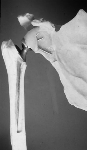
Figure 1: Stanmore Prosthesis
It was not long before modular prostheses were developed and then cementless bony ingrowth prostheses (Copeland, Bi-Modular, McNabb), but essentially these were all the same geometry as the Neer type design. Following the work done by Roberts & Wallace in 1991 [3] and Boileau and Walch in 1997 [4] the wide variation of anatomical morphology at the proximal end of the humerus was noted and prostheses have tried to mimic this. It was noted that the humeral head was offset on the long axis of the humerus and if prosthetic replacement was to mimic anatomy then the prosthetic humeral head must be offset. Therefore any prosthesis that was not made specifically for left or right shoulder could not directly mimic anatomy. The so-called third generation prostheses (eg Tornier) were developed in a modular way to allow for offset version and angulation. But version can vary from -5 to +55 and the equipment to do this and the stock of prostheses required makes this an extremely expensive option.
Hence the stemmed cemented prostheses have really developed in Europe from tumour replacement and in the USA from fracture work. Neither was specifically designed for the treatment of arthritis.
Development of Surface Replacement
If a step forward in shoulder replacement is proposed then we have to review what is wrong with what we've got.
1. Problems with cement
a. Loosening
High incidence of glenoid loosening leaves major problems on the glenoid side with unpredictable bony erosion [5-10]. So much bone may be eroded that revision may be impossible [10, 11]. On the humeral side, although loosening is rare, if it does occur then bony loss and erosion may be catastrophic such that revision may be impossible.
b. Revision Difficulties
If a stemmed prosthesis is inserted in the wrong degree of version to remove this and revise it is a major surgical procedure, which may fracture the humeral stem and require a longer stem prosthesis to gain stability. When cement is used in the humeral shaft of an elderly rheumatoid patient the shaft may crack on impaction of the prosthesis and leakage of bone cement can cause radial nerve problems. The use of cement without a cement restrictor can allow cement to go all the way down to the elbow and preclude ipsilateral elbow replacement, eg in the rheumatoid [12, 13].
2. Problems with a Stem
If an intra-medullary stem is used then a stress riser must arise at the tip of the prosthesis. Shoulder replacement patients are often in the elderly group with fragile osteoporotic bones, particularly in the rheumatoid. If they are elderly and infirm with poor balance then falls are much more likely and hence a fracture at the tip of the prosthesis becomes a much more likely event. This occurs in both the hip and the knee and is now seen in the shoulder in increasing numbers. Fractures around the stem of a prosthesis are very difficult to treat and may cause major problems with revision of surgery.
If arthritis is secondary to a malunited fracture, sometimes it is impossible to pass a stem down the humeral shaft without corrective osteotomies. This has prognostic implications for the result of the shoulder replacement [14].
On occasion the medulla of the humeral shaft may already be compromised by cement and an intra-medullary stem coming upwards from below ie intra-medullary fixation of fracture or a stemmed elbow replacement.
In cementless stem designs, reaming of humeral shaft can also cause fracture [Figure 2].
We have to question why a stem is used at all to fix the humeral prosthesis in arthritis. The majority of stemmed humeral prostheses extend half way down the length of the humerus. There is no scientific evidence to support why this should be so. If a fracture is not present there is no requirement for such a length of intra-medullary fixation. Obviously if there is a fracture at the proximal humerus as in the four-part fracture then a central intra-medullary stem is required as a scaffold to rebuild the shoulder around.
3. Problems with Materials
We know from long term hip and knee studies that the major long term problem with loosening is due to particulate HDP wear debris causing macrophase response and osteolysis. The same is true in the shoulder. Although the surface area of plastic in the shoulder is smaller, because the shoulder is not a captive joint with a fixed centre of rotation, the range of motion of the humeral head upon it is much greater and translational and sheer forces much more important. If one could avoid using HDP at all this would be of benefit for the long term outlook of the shoulder (i.e. hemi-arthroplasty).
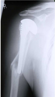
Figure 2: Periprosthetic fracture below a stemmed prosthesis.
Development of and Rationale for Surface Replacement
Going right back to basics we have to reconsider how arthritis effects the joint itself. Obviously there is roughening and distortion of the normal smooth articular surfaces and therefore what is required is a new surface to reconstitute the geometry of the smooth bearing surface. It would only seem reasonable to fix this new bearing surface in the most minimally invasive manner possible. This rationale was attempted at the hip and unfortunately was a failure. However it is successful at the knee. The femoral prosthesis of most knee replacements are in fact a surface replacement of the distal femur.
It is interesting to review why surface replacement of the hip has previously failed. This was essentially a materials problem. If only the surface is being replaced then this is a large weight-bearing surface area of plastic exposed to wear hence the production of plastic debris is greater. This plastic then gained access to the bone cement junction under the cap of the femoral prosthesis, osteolysis ensued, notching of the neck and then failure of the prosthesis. Also to dislocate the hip to gain access to the femoral head destroys part of the blood supply to the femur and reaming of the femoral head destroyed the retinacular vessels. Hence it is not surprising that there was some degree of subsidence and avascular necrosis of the remaining femoral head, although this was not the primary cause. The blood supply to the humeral head is entirely different, with no retinacular vessels and the blood supply arriving via tuberosity muscle attachments. It appears that the main reason that surface replacement of the hip failed is because of increased particulate plastic wear. Amstutz [15], one of the main proponents of surface replacement of the hip notes in 1994 that in his series of hemi-arthroplasties treated by surface replacement of the femoral side, there was no loosening, hence the assumption was made that the cause of loosening was plastic debris access and secondary osteolysis. Partial resurfacing of the femoral head has also been reported by Siguier et al in 'Clinical Orthopaedics and Related Research, 2001' [16]. This appears to be a promising way forward for avascular necrosis of the femoral head. As it is only used on one side of the joint and there is no plastic debris problem.
With respect to surface replacement of the shoulder, Steffee & Moore [17] reported the use of the Indiana hip cup used as a interposition arthroplasty for the humerus. No follow up was recorded for these cases. Rydholm & Sjögen [18] from Sweden reported the results of the 'scan cup' in 1993 in which they used a hemi-spherical cemented cup. This had good clinical results, but they reported a 25% loosening rate at an average of 4.2 years. It was noted that no central fixation peg was used for this cup.
Development of Copeland Surface Replacement design
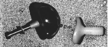
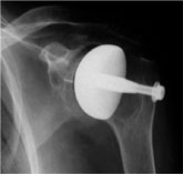
Figure 3a: CSRA Mark 1 Prosthesis
Figure 3b: Mark 1 Prosthesis post operative radiograph
In 1979 work was started to develop a surface replacement arthroplasty of the shoulder. Cadaveric anatomical specimens were measured for size and sphericity of the humeral head. Three prostheses were developed with a 22 mm radius of curvature and three depths of skirt was enough to cover the anatomical variation range. Many different designs were tried on dry bones to try and determine the best method of fixation for this surface cap. From the outset it was designed as a cementless prosthesis. The Mark 1 prosthesis [Figures 3a and 3b] was fixed with a central smooth round peg and a screw passed from the lateral side of the humerus to screw into the prosthesis to act as an anti-rotation bar. This was used clinically on 19 patients but it was soon realised that the fixation was adequate with the impaction stem alone and that the screw was unnecessary. It was also realised that if the prosthesis were to loosen then toggling of this anti-rotation bar would de-associate the tuberosities and this would present a difficult reconstruction revision problem. Therefore the use of the screw was abandoned at an early stage.
The prosthesis was first used clinically in 1986. When the fixation screw was abandoned a better design of central peg was made. The fluted taper fit central fixation peg is critical to the success of the design. The volume of bone removed by the central tapered drill in the humeral head is the same as the volume of bone in the grooved tapered peg. Therefore the outside diameter of the drill is slightly less than the outside diameter of the peg. When the peg is offered up to the bone, the cap has to be impacted home to achieve a tight fit. Initially bone is pushed into the groove and later biological remodelling takes place. From 1993 the whole of the bony surface of the glenoid and humeral components have been hydroxyappetite coated so there is an initial mechanical fix and then later a biological fix with bony ingrowth in to the hydroxyappetite coating [Figure 4]. The original design concept was that the surface replacement would mimic as closely as possible the original anatomy. Therefore very simple instruments were developed to allow anatomical placement of the humeral head. In essence these instruments allow determination of the centre of the sphere based on the angle of the surgical neck as seen at operation. No complicated instrumentation is required to do this and it is never put in a fixed degree of version offset or angulation. Rather an attempt is made to replicate the original anatomical bearing surface.
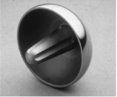
Figure 4: Mark 2 CSRA Humeral Prosthesis.
Development of a Glenoid Prosthesis
Measurements of glenoid anatomy were made on anatomic and cadaveric specimens. A pear shaped glenoid was developed that mimicked the normal anatomy.
In the early 1980s a popular method of fixation of plastic components of joint replacement was by finned interference fit peg. For example, the tibial component of the total knee replacement and the acetabular component of the Ring plastic hip prosthesis. This plastic peg was initially used to fix the Copeland Mark 1 glenoid in 1986. A central drill hole was made and the peg fitted by impaction. The use of all-polethylene impaction fit pegged prosthesis was eventually abandoned for theoretical reasons rather than practical considerations. It was becoming obvious that the main reason for the long-term failure of prostheses was due to polyethylene debris. With the finned design of prosthesis there was a large surface area of plastic presented in direct contact with bone and hence the potential for fretting and debris formation was high. Recent long-term review of these prostheses showed this to be the case in 6 of 19 prostheses that were inserted [19]. When the grooved taper peg fixation of the humeral component was developed the same principal was applied to the glenoid side once again for cementless impaction fitting. From 1993 this has also been covered with hydroxyappetite coating for secondary bony ingrowth fixation [Figure 5].
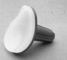
Figure 5: CSRA Mark 2 Glenoid component.