Copeland Shoulder: Operative Technique
1. Approach
Until 1993 we used the standard anterior Deltopectoral approach, however since September 1993 the antero-superior approach as described by Mackenzie [20] has been preferred. The prosthesis is suitable for insertion via either technique. The advantages of the latter approach are smaller and neater scar, shorter post-operative recovery, easier access via rotator interval to the glenoid and better access to the posterior and superior rotator cuff for reconstruction. It also allows for excision arthroplasty of the acromio-clavicular joint and acromioplasty if these were indicated.
If the rotator cuff is intact or a repairable rotator cuff defect is seen an anterior acromioplasty is made with partial resection of the coracoacromial ligament. The coracoacromial arch is left undisturbed if the rotator cuff is extensively torn. If pre-operative radiographs have shown arthritic changes of the acromioclavicular joint and symptoms suggest this is a site of pain, then an excision arthroplasty can be performed at this stage. This further improves the surgical exposure. The rotator interval is identified and longitudinally incised along the line of the long head of biceps to define the insertion of subscapularis. Subscapularis is then detached. The shoulder is dislocated anteriorly. If the long head of biceps if intact it is displaced posteriorly over the humeral head.
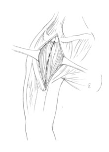
Figure 6: Mackenzie approach – incision with deltoid split no greater than 4 centimetres.
2. Humeral Component
The anatomical neck of humerus is defined and the neck shaft angle is demonstrated. Removal of all osteophytes is essential to define the anatomical neck so that the humeral shaper may be applied to the centre of the head. This is the key landmark for determining anatomical alignment of the humeral component [Figure 7].
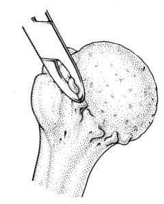
Figure 7: Defining the anatomical neck by removing osteophytes
A sized humeral drill guide is then placed over the head with its free edge parallel to the anatomical neck. The size is determined by a comfortable fit on the head. The guide position should be central on the humeral head and parallel to the anatomical neck, this automatically adjusts for retroversion and inclination. A guide wire is drilled through the centre of the head and out through the lateral humeral cortex, using the drill guide [Figure 8]. The guide is removed and the position of the guide wire is visually confirmed. If the surgeon feels that the guide wire is not central it should be repositioned at this stage.
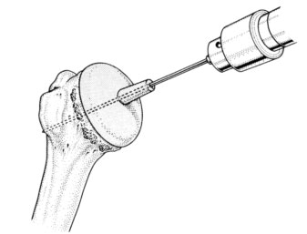
Figure 8: Central guide wire insertion
The appropriate humeral is then passed over the guide wire.Whilst the cutter is rotating, light pressure is exerted on the humeral head to engage the cutting teeth. Cutting shoulde be continued until reamings are seen to extrude through all holes in the shaper. All morselised bone generated is saved for later grafting. The cutter has a safety mechanism whereby it will only resect 3mm of bone per application.
Once the appropriate humeral head size is decided, use the corresponding stem cutter over the guide wire and drill down to but not beyond the shoulder of the cutter to remove the correct amount of bone for the central stem hole. The stem cutter and guide wire are then removed.
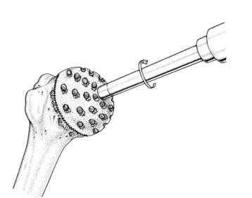
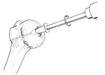
Figure 9: Reaming the femoral head. Figure 10: Central Peg hole
The trial component is inserted. If only a hemi-arthroplasty is to be done, the stability of the humeral component is tested and the range of movement confirmed. Tension of Subscapularis should also be assessed with the shoulder reduced, to ensure no loss of external rotation.
3. Glenoid Preparation
The trial humeral component is left in situ so that the prepared head is not damaged by subsequent retraction. The humeral head is retracted posteriorly with a Murphy's skid. An extensive capsulotomy must be performed, sparing only the superior aspect and providing adequate exposure of the glenoid.
The decision about replacing the glenoid is now made. The glenoid is only replaced if the glenoid surface is affected, incongruent and there is sufficient bone to hold a glenoid component. Pre-operative imaging using an axillary view radiograph and C.T. is also helpful in this regard.
If glenoid replacement is not intended, it is our routine practise to drill the glenoid surface with a 2mm drill bit repeatedly to ensure a fibrocartilage regenerate surface.
4. Glenoid Replacement
The glenoid drill guide is inserted at the exact centre of the glenoid. The glenoid articular surface is prepared with the glenoid surface cutter placed in this pilot hole [Figures 11-13]. If glenoid erosion is severe, anterior or posterior grafting may be required, but this is rare.
In primary and secondary osteoarthritis as much of the sclerotic surface of bone is retained as possible to provide a firm foundation for the prosthesis. Each component is impacted flush with the surface of the bone .The joint is reduced and stability ensured.
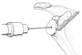
Figure 11: Guide wire insertion into central glenoid
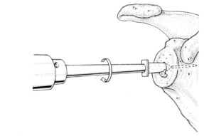
Figure 12: Central peg hole made over guide wire
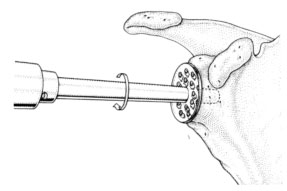
Figure 13: Reaming of the glenoid surface
5. Closure
As the centre of rotation may have been lateralised an attempt is made to gain relative length in subscapularis either with a stepwise cut in the tendon or by medialisation of the insertion of subscapularis to the free edge of the prosthesis. The rotator interval is closed. If there is any rotator cuff deficiency, and this is repairable, it is repaired at this stage.
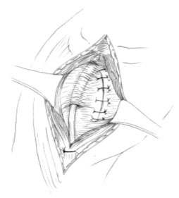
Figure 14: closure of Subscapularis and the rotator interval
6. Post-operative Regimen
Passive movement only is allowed for the first 48 hours and passive assisted for five days. Active movements begin at one week if pain allows and the sling may be discarded at three weeks.
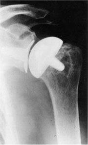
Figure 15: Post-operative radiograph